
Valve Authority
So, what is authority? Intuitively, we can imagine a circuit with a pump, a small restriction, and a large valve with which we intend to control the flow. When we throttle the large valve almost nothing happens when it is near the open position, then the flow changes suddenly near the closed position. The valve is said to have poor authority because most of the time something else is controlling the flow.
The problem with low authority in a control valve is that it produces unstable operation during low-load conditions (ASHRAE 2020, 46.9). Thinking about the valve in the situation above, if we intend to set a precise flow rate it might not happen because a small tap to the handle sends the flow above the target and a tap in the other direction sends it below.
The basic definition of authority is (Petitjean 1994, 146):

Some sources use the version (ASHRAE 2020, 46.8):
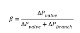
In hydronic systems, though, the actual variable of interest is the heat transfer of the terminal which saturates with increasing water flow if all else stays the same (Figure 1). This leads to a definition of “Practical Valve Authority” denoted by β’:

Here the numerator is the pressure drop of the control valve at nominal flow when fully open, or approximately ((Design Flow)/Cv)2
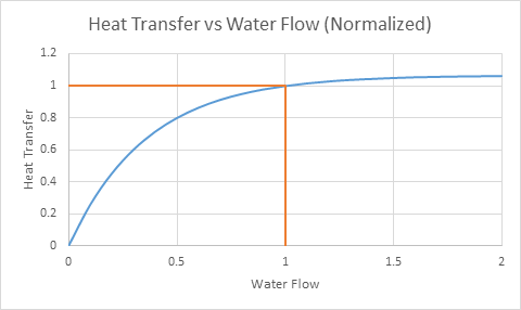
Figure 1
As a result of terminal saturation, even though the shape of the flow curve might be the same at higher pressure, the fact that it is scaled up means that the shape of the heat transfer curve (heat transfer vs stroke) is not the same at different pressures. As already alluded to, the trouble of low authority shows up as unstable control at low flows. The two curves in Figure 2 have the same resistances within the branch but different differential pressures across the branch. As can be seen, the slope of the higher-pressure curve is about twice that of the lower pressure curve in the neighborhood of the closed position. In Figure 7 we see a comparison for the same pressure as the orange trace in Figure 6, with either no balancing, manual balancing, or a flow limiter. It’s important to note that this is the comparison with a pressure that would cause 2x overflow at the fully open position of the control valve without balancing, and thus it’s a fairly large pressure being absorbed by the balancing device (for instance if the nominal flow was at 10 psi, this figure would be at 40 psi so the balancing devices would be absorbing 30 psi at the open position). While the curves are not identical, they all have the same maximum slope near the closed position. The curves in Figure 3 all have the same practical authority β’ as defined earlier, but different values of β according to the definition that ignores the target flow rate.
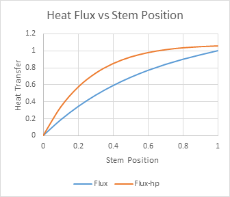
Figure 2: Same β, different β’
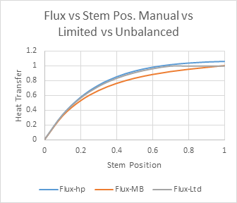
Figure 3: Same β’, different β
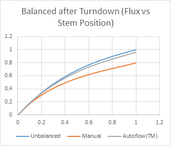
Figure 4: After turndown
Clearly from figures 2 and 3, β’ is a better indication of authority for a hydronic terminal. In Figure 4 we see the same set of balancing situations as figure 3, but at the pressure represented by the blue curve in Figure 2. Once again, the slopes of the curves all converge in the neighborhood of zero showing that β’ is a better indication of authority for a hydronic terminal.