Venturi Balancing Valves

IMI Flow Design sells manual balancing valves based on a fixed venturi element.  This brings up certain questions, of course.

What's a Venturi?

A venturi, at least in this context, is a device which converts pressure to kinetic energy, then converts it back.

To put it simply, it gets narrow, then widens out gradually so as not to stir the water up too much.  As the passage narrows, the pressure goes down.  That might sound confusing, but the fluid has to speed up and it only does that when there's more pressure behind it than in front of it.  As the passage gradually widens, the pressure increases again.  That might also seem confusing, but the fluid will be slowed down by some combination of friction with the wall and increasing pressure: if we avoid too much stirring and make the passage smooth, most of the slowing down will be from increasing pressure.

For a flow meter, we have a connection to the water stream before the passage narrows, and a second port at the narrowest point which we sometimes call the "throat".  The pressure at the throat is lower than the downstream pressure, so the pressure difference we read is higher than the permanent loss that's created.  That last sentence is the whole point.  Figure 1 shows how the pressure changes as water flows through a venturi.  On top is a graph of pressure, and below is a cross-section showing streamlines.
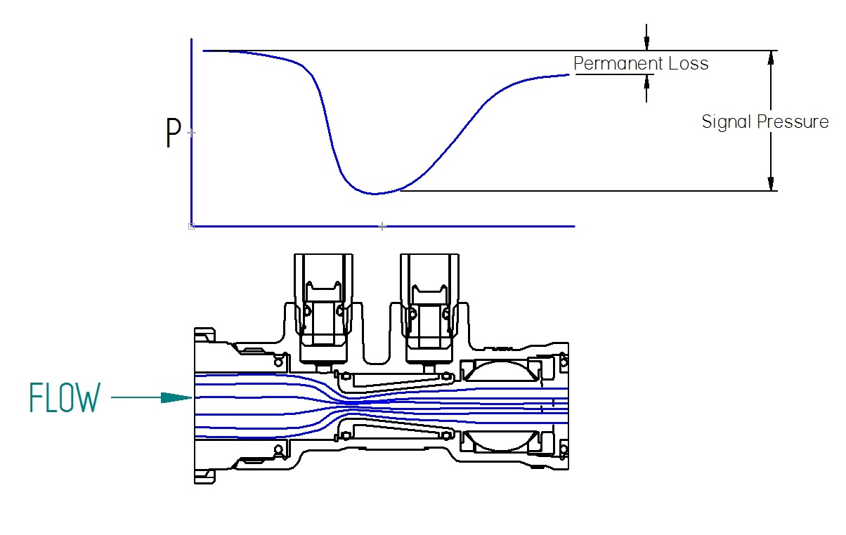
Venturi Flow
Figure 1

Why Use a Venturi?

  1. Because it conditions the flow, a venturi is less sensitive to upstream and downstream conditions than a simple orifice.
  2. The signal pressure on a venturi is higher than the permanent loss.  Whatever signal the balancing company considers acceptable, the pumping loss will be lower with a venturi than with a non-recovering flow restriction.
  3. IMI Flow Design's venturis have been tested to ensure that at any given flow rate the pressure signal is the same regardless where the balancing valve handle is set: so just find the target pressure and dial it in.
  4. IMI Flow Design's venturis are accurate within 3% or better.  This kind of accuracy comes from a simple geometry made with CNC machinery.  Most other kinds of differential pressure flow meters are less accurate because they depend on too many variables.


Modulating Control Valves and Autoflow™

The question comes up regularly: does Autoflow™ interfere with the operation of a modulating control valve? After all, as the control valve closes, the Autoflow will be opening.

In short, of course it will make a difference, but it will not be worse than without the Autoflow™.

Saturation

The rate of heat flux from the water in a coil to the air depends on the temperature difference between the two at the point of contact. Thinking about this, it's clear that the theoretical upper limit of output for a coil would happen when the inlet water temperature was the temperature at the inner surface of the tube over the whole surface. Thus, as flow increases, the heat transfer "saturates" as the temperature of the water leaving the coil gets closer to the temperature entering.

Heat flux saturating
Figure 1

It is not uncommon to design a terminal so that the output under design conditions is 95% saturated with respect to water flow. Under these conditions, doubling the water flow would only make a 4% change in output.

Square Law

Water flow is typically turbulent: It's just a consequence of high density and low viscosity. The result is that when the flow of water through a fixed restriction is reduced to 50%, the pressure drop becomes about 25%.

This is significant, because as the control valve restricts the flow, all other pressure drops in the local circuit become trivial and the control valve takes all the pressure drop. If a balancing restriction of 32 psi is made by a manual valve, at 50% flow it will be making an 8 psi pressure drop. For Autoflow, the pressure drop will admittedly be down to about 0.25 psi. The thing is, though, that the control valve is now seeing an extra 24 psi in one case and an extra 32 psi in the other. Assuming it was sized for 5 psi, this means comparing 29 psi to 37 psi. The square law works the other way when comparing flow at different pressures: the Autoflow system would flow about 63% of maximum if the manual valve is at 50% of maximum.

Net Effect

With a properly characterized control valve, the heat transfer as a function of stem position is almost exactly the same whether manual balancing, automatic balancing, or no balancing is used:

Flux with Autoflow, manual, or nothing
Figure 2

This might prompt the question why to balance. The answer lies in comparison of the water flow under the same conditions:

The horrors of overflow
Figure 3

So, while the thermal result as a function of stem position is almost the same, the unbalanced system will waste water flow ridiculously when the demand is near to the design conditions. So if the water flow is so much higher, why is the heat transfer not? Simple. The "delta T" of the water is very low for the unbalanced system.

Summary

Even in the case when Autoflow™ must absorb 32 psi to prevent overflow, it does not significantly affect the performance of the control valve.  This is because regardless of how the system is balanced, the control valve will see very nearly the full pressure drop across the circuit by the time it throttles to half flow, which is typically 80% of heat transfer, and overflow contributes very little added heat transfer.

Thus, a commonly cited argument against automatic balancing is a misconception.  The advantages, however, are not.  An automatically balanced system prevents wasted circulation under all conditions while allowing variable speed pumps to ramp back without starving the system.  Automatic balancing also allows the system to work correctly from the moment it starts up, without a complex adjustment procedure.  Finally, the use of fixed flow limiting cartridges such as Autoflow™ prevents uninformed personnel from unbalancing the system.

Traction Control

Picture yourself on a soggy dirt road. For some reason you've stopped and want to get going again. Unfortunately, when you press the gas, one wheel spins. Pressing the gas more just makes it spin more and the car goes nowhere. Then you suddenly remember your car has traction control and activate it. The system applies the brakes to the slipping wheel so that power can go where it will do the most good.

Some say that adding balancing devices is like driving with the brakes on. In a way they're right: balancing valves can only make the water flow slower in the circuit they're connected to. Below we'll explain why one would want to do that.

How Can I Have Spinning Tires in a Hydronic System?

The output of a coil "saturates" as the flow of water through it increases. That will be explained later for those interested. The point is: beyond a certain point more water flow helps very little in cooling or heating the room. Too much is pretty much like a spinning tire. If there's twice the design flow, there might be only 5% more heat transfer while another room is being robbed of capacity.

Hydronic Traction Control

As with traction control on a vehicle, we slow the flow through the wild circuit so that power can go where it will do more good. Autoflow™, in particular, is good as traction control. If overflow would otherwise happen, Autoflow™ will add just the right restriction to prevent a large waste of flow. When the pump slows down or the control valve starts throttling so that an overflow would not happen, Autoflow™ opens fully so that it creates very little restriction. As the flow continues to reduce, the pressure drop of the balancing device reduces according to the square law, so at 50% flow the pressure drop through the balancing device is ¼ of what it is at full flow.

Why Does a Coil's Output Saturate?

Heat transfer is dictated by the temperature gradient and some coefficients. This means that for a given incoming air temperature, air flow, and water inlet temperature there's a theoretical limit for the heat transfer. If we imagine that the inner surface of the coil is all at the inlet water temperature, clearly the coil could not transfer more heat than what we would calculate. Also clearly, that state will never be reached: as we transfer heat the water changes temperature. For a typical air conditioning coil, the design flow is often as much as 94% saturated meaning that it produces 94% of that impossible theoretical limiting heat flux.

082714_1255_TractionCon1


So, if a terminal flows twice what it should, the heat flux increases less than 6%. This remains true if it flows 4 times design flow. All that extra flow does is make noise, waste pump power, and make the chillers less efficient.