

Three-way valves are not constant flow devices. When three-way valves are manually balanced, there can be a substantial overflow. With AutoFlow regulators there are no overflows, and no overflow means energy saved. The diagrams below show how the three-way valves are balanced and how AutoFlow saves energy.
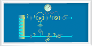
Manual Balance Three-way Coil
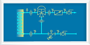
Automatic Balance Three-way Coil
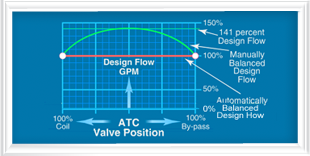
Overflow Wastes Energy
Manual balancing requires the following steps:
- A differential pressure gauge is placed on the manual balance valve.
- The three-way ATC valve is driven to the full open position with all the flow through the coil.
- The manual balance valve is adjusted to achieve the “design flow” and the memory stop is locked in place. The D.P. gauge is left in place.
- The ATC valve is driven to the full by-pass position.
- The ball valve in the by-pass is adjusted to achieve design flow through the by-pass and the memory stop on the ball valve is locked in place.
AutoFlow circuit requires the following steps:
- The proper AutoFlow valve, factory-labeled for the specific terminal unit and GPM, must be installed as shown.
- Design flow is achieved as soon as the pump is turned on.
- Verification of the design flow can be achieved by reading the differential pressure across the AutoFlow valve. A reading above two psi and below 32 psi indicates that the design GPM is flowing.
Saves 10%-20% of BHP for life of the building.
The graph below shows that the manual balance points are at the extreme ends of the ATC valve operating range. At midrange, where the valve operates most of the time, the overflow can range from 10-50 percent with manual balancing. The AutoFlow regulator keeps the flow at design GPM regardless of the valve’s position.